
Rotary Tables – 4 Steps For Alignment with vertical spindle
For a look at the rotary tables we sell, please visit this page here.
When using a rotary table there are four simple steps that are invariably necessary. It is very easy to overlook the simplest alignments necessary. Most rotations will be with reference to some particular point. Usually this will mean setting the table to zero – the zero must be at the fiduciary mark.
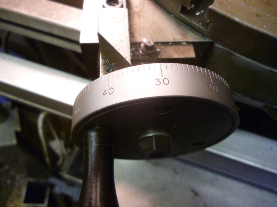
Step One – Zeroing a rotary table
Before doing anything else with a rotary table it is always worth setting it to zero. The table is turned so the fiduciary mark on the base is pointing to 0 degrees on the side of the rotating part.
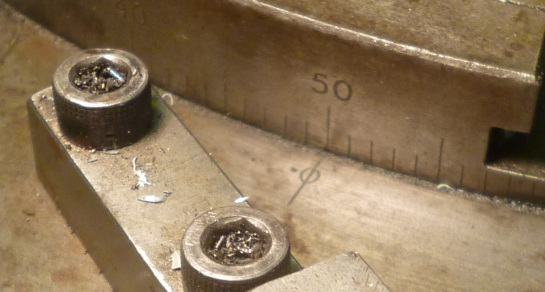
If this is done it is unlikely that the zero on the dial lines up with the marker. This can usually be adjusted by rotating the part with the calibrations on it whilst holding the handle from moving..
Step two – “squaring” the rotary table
Sometimes it is necessary to make cuts into a workpiece mounted on a rotary table by moving the table in the clockwise or anticlockwise directions and it is necessary to align the table so that such a cut occurs when the fiduciary mark on the table is at a particular angle to the milling table.
In this case the next step is to clamp the rotary table to the table. It might not seem obvious but, ideally, a line from the center to the fiduciary mark should be at right angles to the table. This is not as easy as one might imagine.
This can be done with the tool shown.
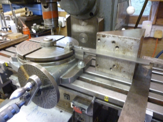
This device consists of a spigot that fits the hole on the rotary table. It has an arm fitted to it. One edge of this arm is aligned so it goes from the center of the rotary table to way beyond the edge of the rotary table. It has a clamp so it is bolted to the rotary table. It has a bit hanging down so it can be aligned at 270 degrees on the rotary table.
This arm can be aligned with the milling table using an angle plate and a square as shown above. The rotary table with the device attached is moved till it is square and is then clamped to the milling table.
On some tables the zero on the table can be adjusted. If so this has to be done when the rotary table is square to the milling table table.
step three – Aligning the rotary table with the milling table
If the rotary table has been “squared” then it will already be clamped to the milling table. In this case it is best centered using the DTI on an arm tool.
If it was not necessary to “square” the rotary table then it will not be bolted to the milling table. In this case the easiest way of aligning it with the spindle is by means of spigots.
The rotary table is now centered and aligned rotationally it is now possible to tighten the bolts up. Check the alignments still work ie the one in the milling chuck still slides in and out of whatever other spigot it is fitting into.
Four – recording the position
The final step in aligning the rotary table is to record the position by setting the x and y DRO’s to zero.
The table can be moved anywhere but it will always be possible to restore the centering by moving the table till the x and y readings are both zero.
Recent Posts
-

Introducing Paypal = Pay in 4 !
We are now offering the option of selecting PayPal Pay in 4 at checkout to pay for your purchase. Mu …1st Jun 2023 -

Reaming Tie Rods & Ball Joint Reamers
Quick Guide on Tie Rod/Ball Joint Reamers: Understand the …7th Mar 2023 -
Unimills = Why they are the best of both worlds
When it comes to machining, choosing the right tool can make all the difference in achieving the per …7th Mar 2023