
Lathe Alignment Guide For Beginners
Aligning The Lathe - Beginners Tips & Guide
Most lathes, however badly they are set up, will be able to do some useful work. But to do any serious work it is essential that the lathe is setup properly.
In practice it is not always possible to do this perfectly. It is, therefore, important to understand how each adjustment affects the accuracy of the lathe.
When aligning a lathe each process has to be done in the order listed below. In general there is little point moving onto the next step until the current one has been completed satisfactorily. Well, that’s the idea. But it becomes obvious that even the first step is going to be a problem for many people. The conclusion has to be that the steps have to be done in the following order and each step has to be done as well as possible.
Curious point
It will be noticed that much is said about the alignment of, for example, the axis of the headstock with the axis of the tailstock that this is only mentioned with reference to the alignment in the vertical plane. It is not that the horizontal plane does not matter. The reason is that if the cutting edge is on the side of the workpiece, the position of this edge in the horizontal plane is crucial whereas the position in the vertical plane is very important but not as crucial.
Because of this the height and the horizontalness of the spindle and the barrel of the tailstock are usually determined and set during the manufacturing of the lathe. These can be assumed to be always good enough.
Steps in setting up the lathe
1. mounting the lathe on the floor
2. levelling the lathe
3. aligning the headstock
Setting the bed so it is level
What is really happening when the bed of the lathe is set to be level is that the surface is flat – ie – not twisted.If the level is set along the lathe on either side and it is flat and across the bed at either end and it is flat then it is unlikely to be twisted.
Very small lathes such as those used by watchmakers might only be support at one point. Larger lathes such a a Myford are only supported at two points.
Bigger lathes than this are often supported by two bolts at either end. Adjusting these is not as easy as one might imagine. One approach is to assume that one bolt is set as required. Make this the most inaccessible bolt. This is locked. This leaves three to be adjusted. It is very easy to set the lathe to very close to what is required. Set the bed longwise to be roughly level. Set the bed to be roughly level across the bed.
For most smaller lathes this requires a level that can detect a difference of 0.1mm in 1 meter. If the bed has inverted V-shapes for guiding the saddle and tailstock then parallels or equal thickness can be put on either side of the bed and the level placed on top of them to test the bed for flatness.
When adjusting any of these bolts it will have an impact on all of the others. This means the process is an iterative one. One has to go round and round until the bed is level both directions. Each iteration will involve smaller and smaller adjustment. On a larger lathe the bed is so rigid it is quite possible for it to be adjusted so that the locked bolt is lifted in the air.
When all of this has been done all of the bolts should be locked. At this point it will often be found that doing this will itself cause a slight movement of the lathe. Some skillful adjustment should be able to solve this.
On very large lathes it is not possible to make a bed that can support its own weight. An example of this is a small DSG lathe. Most of the weight is in the the headstock end. This is solved by have four bolt to take the weight of the headstock and two to take the weight of the rest of the bed. This is probably done the same way. Locked one bolts then adjust the rest so it is roughly right and then go round and round making small adjustments till it is flat along the bed and across the bed.
Adjusting the bearings
The bearings for the spindle on most lathes are adjusted by means of a pair of nuts on the left side of the headstock.
fig nuts for adjusting the spindle bearings
The nut on the right has to be adjusted so that there is no play radially or axially measured with a dti on the spindle and the spindle is still free to rotate. Furthermore this rotational movement must be smooth all the way round. It should not be possible to feel any differences in its resistance to being rotated at any point as it is turned by hand. This nut will need to be locked by the nut to its left once it is adjusted. It is always necessary to check the adjustment again after doing this locking. There is no point in proceeding beyond this point until this condition is fulfilled. Once this has been achieved the spindle has a defined axis of rotation. This does not mean anything can be fitted to it and then will be square, concentric or anything else.
Aligning the headstock
For the lathe to turn parts that are parallel, the axis of the spindle must be parallel to the bed of the lathe. On some lathes this is determined by the construction of the lathe when it is being manufactured. On lathes where this can be adjusted then it has to be adjusted. If the taper socket on the spindle was perfect then it would be possible to fit this socket with a test bar with a taper on it. Whether the headstock is aligned or not a test bar like this, if touched with a dti, must show zero runout. If it does not then the socket is probably damaged. It might be possible to clean it up with a tapered reamer. Method 1 – using a test bar in the tapered socket in the spindle A test bar is fitted into the socket in the spindle and banged in with a soft headed mallet. A DTI is setup against the far end of the test bar. The spindle is rotated by hand. The change in the reading on the DTI should not be more than 0.01mm in 100mm. This merely tests that the axis of the test bar is coaxial with the axis of the spindle. If it is not then either the test bar is faulty or the taper socket in the spindle might be spoilt. Try method 2. Method 2 In the end most lathes do not use the taper for anything other than holding a center for turning between centers. In these cases a center can always be fitted to the spindle, banged in, and tested with a dti.
turning a center so that it is concentric
If the center is not close to perfect it can usually be turned using a carbide cutter. This will produce a surface that is perfectly concentric with the axis of the spindle. however if the center needs to be machined like this it can never be relied on being accurate again once it has been removed from the spindle.
Aligning the tailstock
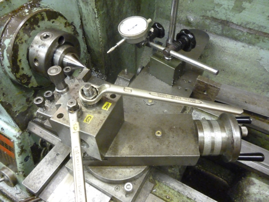
If the headstock is parallel with the bed and the center in the spindle is coaxial with the spindle then it is possible use this to align the tailstock. This can be done using a test bar.This is placed between the center in the spindle and a center in the tailstock. The edge of the test bar is then tested along its length with a dti. This should be correct to 0.01 in 100mm. We stock 1MT, 2MT, 3MT & 4MT Lathe alignment test bars which you can buy here.
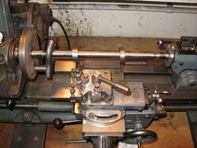
Test bar between center in headstock and center in the tailstock
What if the socket in the tailstock is seriously damaged? If a good center is put in the socket it will always go in same which ever way round it goes in. Because of this the tailstock always appear right using the test bar method. It also follows from this that a rotating center in the tailstock is always correct enough. It will be noticed that really one would expect the height along the testbar to be the same. But this has not been tested. firstly because it is fixed by the height is the axis of rotation of the spindle and the height of the axis of the center in the tailstock. Neither of these are adjustable. Anyhow, since all cutting is done on the side of the workpiece very slight differences in height will make not difference to the diameter of the workpiece. Errors might be caused by wear of the tailstock along the bed of the lathe and by wear on the barrel of the tailstock. Where the tailstock is guided along the bed by an inverted V it is probable that it will move in a straight line. Where the tailstock is guided by flat and vertical surfaces, if these are worn, then it might not move in a straight line. In this case the tailstock can be set so it is correct but this will only be true at one particular position. In this case, a workpiece is can be turned to be parallel so long as the length of the workpiece is that same as the length of the test bar that was used to set the tailstock to be parallel.
An exception
On a lathe where the headstock can rotate it is still possible to make highly parallel parts. This can be done if the part is held between centers.The tailstock is aligned with the center in the headstock. any part now turned between these two centers with be parallel.
Recent Posts
-

Introducing Paypal = Pay in 4 !
We are now offering the option of selecting PayPal Pay in 4 at checkout to pay for your purchase. Mu …1st Jun 2023 -

Reaming Tie Rods & Ball Joint Reamers
Quick Guide on Tie Rod/Ball Joint Reamers: Understand the …7th Mar 2023 -
Unimills = Why they are the best of both worlds
When it comes to machining, choosing the right tool can make all the difference in achieving the per …7th Mar 2023