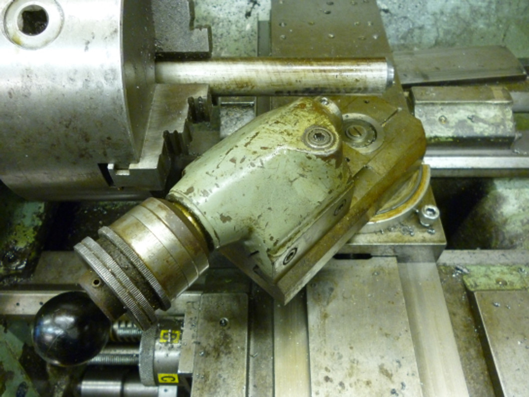
Ball Turning In The Lathe Pt 2 - Operating Attachments
Using a ball turning attachment
A ball turning attachment is an easy way of making a round shape. Its main limitation is there is a very distinct limit as to the diameter of the work piece as well as the angle of the surface that can be made. A ball turning attachment is really just a mechanism that cause the cutting edge to follow a circular path which is the outside of the ball being cut.There are two different ways this can be done. The cutting edge can turn in the horizontal plane or it can turn in a vertical plane lying along the axis of the lathe..
Alignment of a ball turning attachment
To produce an accurate ball the (vertical) axis of rotation of the ball turning attachment must be in the same vertical plane as the axis of rotation of the spindle of the lathe.
For best results a four-jaw chuck or collects are needed.
Suppose the workpiece is centered in the chuck. The outside is turned down as required to the right diameter.In this case, it is important to line the attachment very carefully otherwise it might not be possible to produce a perfect ball. If a perfect ball of exactly the right size is required then one could turn the workpiece down to slightly larger than the required diameter.
The cutter is set to just touch this on one side as shown.
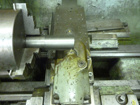
Setting the cutter on one side
The saddle is moved right and the tool is swung round, if possible to the other side.
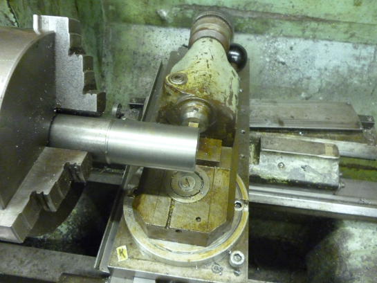
The position of the cutter is adjusted as is the position of the attachment in the in/out direction till the cutter just touches the surface of the bar in both positions. The cross slide is then locked.
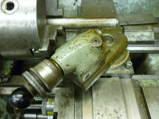
It can easily be seen in this photo how the front of the dovetail has been cut off so as to make it possible to make slightly bigger spheres.
Having done this it is possible to set the attachment along the bed of the lathe. It is not easy to set this accurately. But in most cases it is possible to set the cutter in one of the in/out position and align the point of the cutter to the end of the work piece. This sets the vertical axis of rotation of the attachment to the end of the work piece. The saddle is locked. The top of the dovetail on the attachment is moved right away from the work piece by very slightly more than the radius required. The saddle is then moved till the cutter touches the work piece. The saddle is locked again. The tip of the cutter is now very near the last cut that will be made. The cutter is moved away from the work piece so the first cut will just clip the corners of the end of the work piece..
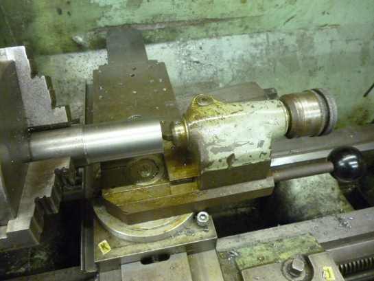
Setting the cutter
The cutter is made from a piece of square HSS. It is a simple V shape. But the V must be center of one side of the piece of HSS. The “square” hole in the attachment is slightly higher than it is wide so the height of the cutter can be adjusted as required. The cutter, made like this, will not have any rake but it will still cut.
When trying to cut a ball with the largest possible “angle” the cutter needs to have the whole of the left side cut away.
Turning whole balls
This method can make a ball on a shaft where the “angle” the ball makes is about 270º out of the 360º possible. The limit is largely the attachment hitting the chuck. It will also be noticed that to get this angle the ball has to be made a long way out from the chuck. To get the best possible result the left side of the cutter needs to be removed.
Using linkages to control the position of the cross slide
If a linkage can be fitted to the bed of the lathe at one end and connected to the cross slide at the other end then if the cross slide is moved this linkage will make the saddle move left/right so the cutter moves in a circular manner.
The forces on the linkage are such that only relatively large radius’s can be cut using this method.
The point that the linkage pivots about on the bed of the lathe will determine the position of the center of the arc the tool moves in. The radius of the surface produced will be determined by the length of the link plus the radial distance of the cutting tip from the path the link on the saddle takes.
The diameter of the work piece is limited by the swing of the lathe. For a convex surface the link is on the left of the saddle. Since the work piece will be just to the right of the chuck the radius that can be cut varies from next to nothing to the distance from the left end of the bed of the lathe to somewhere just to the right of the chuck.
The linkage has to be fitted on the bed so its center is directly below the axis of rotation of the spindle otherwise a part of a doughnut will be formed.
Ball turning with the cutter moving in the vertical plane
The usual way of doing this is to make the attachment so that it fits the tool post. The cutting part is on a dovetail slide. The position of this determines the diameter of the cut. In the example shown below the dovetail part was taken from a small dividing head.
Linkages used to make concave surfaces
If the linkage is to the right of the saddle the surface will be concave. The length of the linkage can be from next to nothing to the distance between the right side of the saddle to the end of the bed of the lathe.
Limit on using linkages
When using a linkage as described above one limit is that it will only work if the cutter is moving at an angle to the work piece of not more than about 30º. This means that only parts of a sphere can be turned like this.
Recent Posts
-
Introducing Paypal = Pay in 4 !
We are now offering the option of selecting PayPal Pay in 4 at checkout to pay for your purchase.&nb …1st Jun 2023 -
Unimills = Why they are the best of both worlds
When it comes to machining, choosing the right tool can make all the difference in achieving the per …7th Mar 2023 -
Reaming Tie Rods & Ball Joint Reamers
Here's a guide on determining which ball joint reamer you need for tie rods: Understand the purpose …7th Mar 2023
